High Voltage Power Supplies, Plasma Physics
ISEPS for SPIDER
Ion Source and Extraction Power Supplies (ISEPS) for ITER
The International Thermonuclear Experimental Reactor (ITER) is an international research effort aimed at developing fusion as an abundant energy source with low environmental impact. The facility is under construction in Cadarache, France, and will feature an experimental Tokamak reactor. The EU, U.S., China, Japan, South Korea, India and Russia are all participating, with the goal of testing the integrated technologies, materials and physics regimes necessary for commercial production of fusion-based energy in the future.
To achieve fusion on Earth, the plasma where the reaction takes place must be heated to about 150 million degrees Celsius. One of several systems used to achieve these extreme temperatures is a “neutral beam injector” that injects high-energy particles of the same kind present in the reactor to produce heating. ITER will make use of two neutral beam injectors of 16.5 MW to create, accelerate and finally neutralize the ions before they enter the plasma.
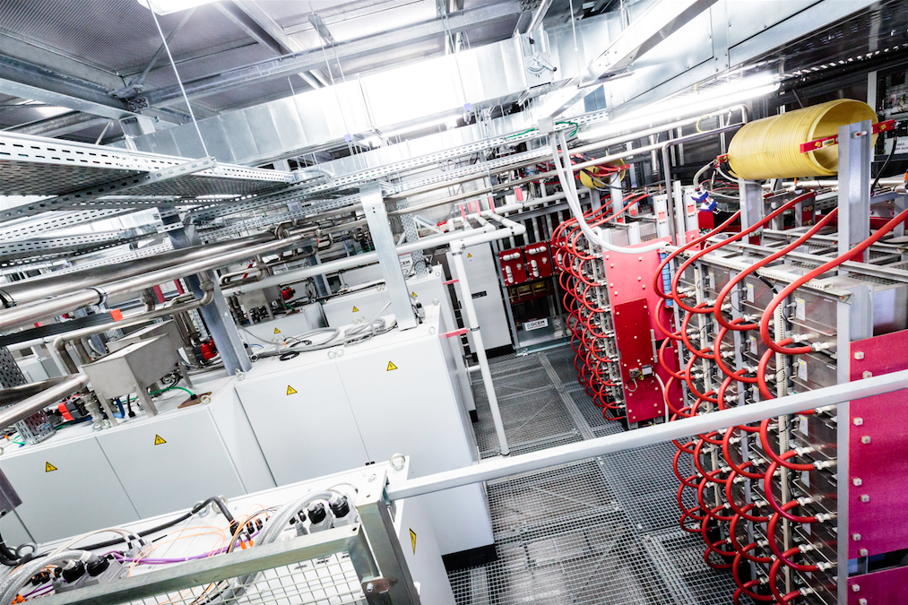
In the first two stages of the neutral beam injector, the ion source generates a cloud of negative Deuterium ions which are then extracted using the extraction grid. OCEM Power Electronics was commissioned by the organization Fusion for Energy, which is overseeing Europe’s contribution to ITER, to produce the Ion Source and Extraction Power Supplies (ISEPS) system to power these steps.
Download the ISEPS Case Study
KEY FEATURES
1. Extraction Grid power system (ISEG)
- Capable of 12 kV at 140 A, voltage ripple < ± 1%
2. Four radiofrequency generator systems (ISRF)
- Four generators 0.9 ÷ 1.1 MHz, each 200 kW on 50 Ω load (160 kW ± 30° loads)
3. Source Support Power Supplies power system (ISSS)
- Plasma grid filter power system, 0÷5000 A, 15 V
- Bias power system, 600 A, 30 V
- Bias plate power system,150 A, 30 V
- Two core snubber bias power systems, 200 A, 50 V each
- Starter filament bias power system, 4 A, 160 V
- Six Caesium oven power systems, 4 A, 160 V
4. Power distribution (ISPD)
- Oil transformer rated 5MVA, 22/6.6kV insulated at 100 kV DC
- Circuit breaker and distribution boards at 6.6 kV and 400 V
- Resin cast transformers (200 kVA / 6.6 kV and 130 kVA / 400 V) to feed the 400 V loads grouped into two insulated subsystems
5. Local Control systems
- “Slow control system” for configuration, supervision and monitoring of the ISEPS
- “Fast control system” for management of fast controls, feedback regulations and protection functions, interlocking of power system internal faults, and all high-speed communications
